

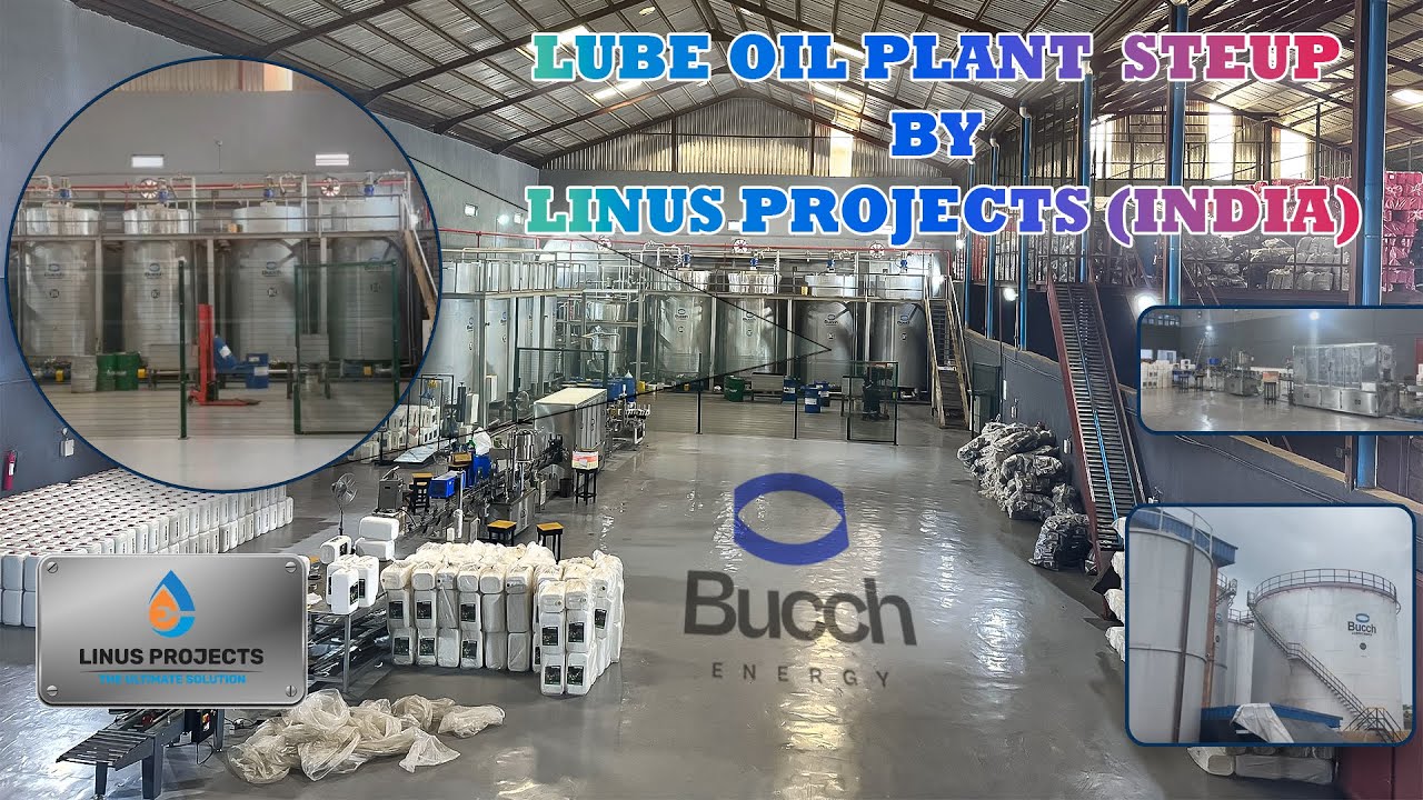
Revolutionising Lubricant Production: State-of-the-Art LUBE OIL BLENDING PLANT Solutions
In today's dynamic industrial landscape, the demand for high-performance lubricants is continually growing. At the forefront of meeting this demand are advanced LUBE OIL BLENDING PLANT facilities. These specialised operations are the bedrock of lubricant manufacturing, meticulously transforming base oils and additives into the essential fluids that keep machinery and engines running smoothly, efficiently, and sustainably.
WHAT IS A LUBE OIL BLENDING PLANT?
A LUBE OIL BLENDING PLANT is a sophisticated manufacturing hub dedicated to the precise formulation of lubricating oils. It's where raw materials—primarily meticulously selected base oils and performance-enhancing additives—are combined in exact proportions using advanced technology and equipment. These plants are engineered to achieve specific viscosity, thermal stability, and protective properties, tailoring the final lubricant to meet stringent industry standards and diverse application requirements. Capacities can range from modest daily outputs of 5 MT to robust production of 300 MT per day, catering to a wide spectrum of market needs.
The Core Components of Lubricant Manufacturing
Base Oils: These form the foundation of any lubricant. Derived from highly refined crude oil or advanced synthetic compositions, base oils are the primary liquid medium. They are typically a by-product of the crude oil refining process. The selection of base oil (e.g., Group 1, Group 2, Group 3, GTL) is critical and depends heavily on the operating conditions and performance demands of the final product.
Additives: These are the crucial chemical enhancers that impart specific functionalities to the base oil. Without additives, a base oil's lubricating properties would be limited. Additives can enhance oxidation stability, prevent wear, improve detergency, reduce friction, manage viscosity, and much more.
TYPES OF BASE OILS:
- Group 1
- Group 2
- Group 3
- Gas-to-liquids (GTL)
- SN500
- SN 150
- SN 70
- Bright stock (BS)
The synergy between base oils and additives, often in ratios ranging from 85:15 to 90:10, defines the lubricant's ultimate performance. This precise blending process is the core function of any modern LUBE OIL BLENDING PLANT.
Advancing Lubricant Production: Our Expertise
We offer comprehensive solutions for establishing and optimizing LUBE OIL BLENDING PLANT operations, encompassing cutting-edge blending systems, precision equipment, and intelligent automation.
Advanced Blending Systems: The Heart of the Operation
The effectiveness of a LUBE OIL BLENDING PLANT is directly tied to its blending technology. We specialize in a range of sophisticated systems designed for accuracy, efficiency, and flexibility:
LINUS PROJECTS

-
Blending Agitator
-
Automatic Batch Blending (ABB)
-
Inline Blending System (ILB)
-
Simultaneous Metered Blending Unit (SMB)
-
Skid-Mounted Lube Blending Plant
-
Pigging Unit
-
Ultrasonic Blending Technology
-
VI polymer dissolver
-
Automation SCADA for Lube plant
-
Laboratory Equipment
LUBRICANT BLENDING PROCESS:
01.
BLENDING SYSTEMS
02.
VI POLYMER DISSOLVER
03.
DECANTING UNITS
04.
LABORATORY EQUIPMENTS
01. LUBE OIL BLENDING SYSTEMS

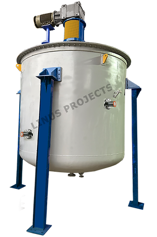
BLENDING AGITATOR
An oil blender is a specialised industrial machine used in a Blending Plant to precisely mix base oils and additives to create various lubricant formulations. An oil blender typically consists of a robust framework or chassis that supports its components and machinery. At the centre of the blender is the blending vessel or tank, which serves as the primary container for the blending process. This vessel is designed to hold significant volumes of base oils and additives and is equipped with mixing mechanisms to ensure thorough blending and uniform distribution of ingredients. Capacity ranges from 1 MT to 20 MT Blenders.
The blending vessel is constructed from either Mild Steel or Stainless Steel IS 2062 material and features an open top design with a partially dished bottom. A hinged top lid is provided for easy access to the main blender. At the bottom, a ball valve is installed for discharge purposes, along with a sample valve for quality control. Surrounding the main blender is an MS jacket, complete with inlet, outlet, drain, and vent fittings. Additionally, each vessel is equipped with a temperature probe and fittings to ensure precise temperature control.
Our blenders are meticulously engineered to comply with ASME standards and are capable of producing various grades of lubricants, including engine oil blending plant, gear oil, hydraulic oil, special-purpose oil, marine oil, and viscosity improvers. To facilitate precise dosing of additives, each blender is equipped with an additive dosing bunker.
The output shaft of the gearbox is connected to a stator housing, which includes bearings, oil seals, and gland packings to ensure smooth operation. The blending vessel is designed to withstand temperatures of up to 200˚C and is insulated with rock wool and clad with GI sheets for enhanced thermal efficiency and durability.
FEATURES:
1. Precision Mixing: Oil blenders are engineered with precise mixing mechanisms, ensuring consistent blending to achieve the desired composition and quality.
2. Versatility: These blenders are adaptable to a wide range of base oils, additives, allowing for flexibility in production to meet diverse industry requirements.
3. Customisation: Many oil blenders offer customizable blending parameters, enabling operators to adjust mixing speeds, agitation levels, and other settings to optimise blending performance and meet specific product specifications.
4. Automated Controls: Advanced oil blenders feature automated control systems that monitor and regulate blending parameters such as mixing speed, temperature, and ingredient ratios, ensuring accurate and repeatable blending results.
5. Easy Maintenance: Oil blenders are designed for straightforward maintenance, with accessible components and features that facilitate routine upkeep tasks to minimise downtime and sustain optimal performance.
6. Safety Measures: These blenders incorporate safety features such as emergency stop buttons, safety interlocks, and protective guards to ensure operator safety during operation.
7. Hygienic Design: Constructed from sanitary materials and compliant with stringent hygiene standards, oil blenders prevent contamination and maintain the purity of the products.
8. Scalability: Oil blenders are scalable to accommodate varying production capacities, from small-scale operations to large-scale manufacturing facilities, ensuring suitability for different production demands.
Overall, oil blenders play a pivotal role in the manufacturing process, providing precise blending capabilities, flexibility, and advanced features to produce high-quality lubricants for diverse applications in industries worldwide.
ADDITIVE MIXING PORT
An additive dosing tank in an oil blending setup is a specialized vessel integral to the manufacturing process. In the context of an oil blending tank, an additive dosing tank is a crucial component designed to precisely measure and introduce additives into base oils during the blending process. Constructed from durable materials like stainless steel or Mild Steel, these tanks are engineered to withstand the chemical properties of various additives and ensure the integrity of the lubricant oil formulation.
The additive dosing tank is strategically positioned within the oil blending setup, typically adjacent to or integrated with the main blending vessel. It features dedicated inlet ports or connections through which both base oils and additives are added to the tank.
Internally, the additive dosing tank is equipped with mixing mechanisms such as agitators or stirrers, powered by motors or pneumatic systems. These mechanisms ensure thorough blending and homogenization of the base oils and additives, facilitating the creation of a uniform quality formulation.


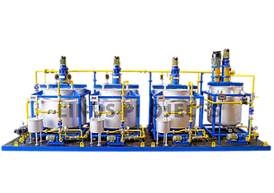
LUBRICANT OIL, Automatic Batch Blending System(ABB)
Advanced automation system featuring Smart Blend Software, DDU (Dilution Dispensing Unit), transfer pumps, TFH (Thermic Fluid Heater), filters, laboratory setup, and professional installation services. Implementing computerised technology has revolutionised blending processes, ensuring consistent product quality, minimising re-blending and laboratory costs, and maximising blend vessel utilisation.
One of the primary advantages of automatic batch blending is its ability to achieve precision mixing. Automated systems employ advanced technologies to accurately measure and control the quantities of each ingredient, ensuring that the blending process adheres meticulously to predefined formulations. This precision is crucial in industries where product specifications and quality standards are paramount.
Consistency is another crucial characteristic of automatic batch blending. These automated systems consistently deliver uniform results across multiple batches by following meticulously programmed recipes and predefined parameters. This consistency is critical to maintaining high product quality and meeting stringent industry standards. It also contributes to the reliability and predictability of the manufacturing process.
Efficiency is a fundamental aspect of automatic batch blending. Automation significantly streamlines the blending process, reducing the reliance on manual intervention. This not only minimises the risk of human errors but also optimises the utilisation of resources, leading to increased overall efficiency in production. The streamlined and automated nature of the process contributes to faster production cycles and improved throughput, ultimately leading to significant cost savings.
BENEFITS OF AUTOMATIC BATCH BLENDING SYSTEM:
1. Enhanced Product Quality: Utilising computerised technology ensures consistent product quality.
2. Compliance: ABB facilitates ISO 9002 and ISO 14000 compliance.
3. Optimum Production: The system optimises production quality with excellent dosing accuracy and repeatability.
4. Process Flexibility: ABB enables meeting just-in-time requirements and offers process flexibility.
5. Waste Minimisation: ABB helps minimise waste generation, reducing environmental impact.
6. Lower Maintenance Costs: The system lowers maintenance expenses and is designed specifically for unit requirements.
7. Improved Profitability: ABB enhances plant profitability through efficient operations.
8. Reduced Manpower Costs: Semi-skilled labour can efficiently run the plant, lowering workforce expenses.
9. No Re-blending: ABB eliminates the need for re-blending, saving time and resources.
10. Accurate Management Budgeting: The system allows for accurate planning of grades and production volumes before real-time processing.
In conclusion, automatic batch blending represents a technological leap forward in the manufacturing landscape. It has become an integral and preferred method for industries that prioritise precision, consistency, efficiency, flexibility, traceability, and reduced wastage in their production processes. The adoption of automated batch blending systems underscores a commitment to delivering high-quality products reliably and sustainably, while also reaping the numerous benefits it offers.
INLINE BLENDING SYSTEM (ILB) FOR (LOBP)
The ILB (Inline Blending System) machine is fully automatic with a continuous blender and an auto-cleaning system. The system uses a group of VFD (Variable Frequency Drive) controlled pumps, flow meters and automated valves. The entire process is automated and PLC-controlled with a SCADA interface. The Inline Blending System can be operated by a smartphone or a built-in touch screen with wi-fi connected to a computer system. The whole process of ILB (Inline Blending System) is accurate and very easy to operate.
ILB (Inline Blending System) is composed of several dosing modules. They are used for blending large batches that require consistent quality. ILB is connected to input and output lines, where input lines are connected with raw material storage tanks, that is, base oil & additives, and output lines are connected with oil storage tanks or filling areas. ILB mixing technology eliminates the need for bulk storage tanks and speeds up the rate of production, reducing capital cost and making it easy to pack and ship consistent quality finished products.
Advantages of the Inline Blending System
1. Large Blending Volumes.
2. Consistent quality
3. Minimum contamination occurs
4. Operated by smartphone or built-in touch screen
5. Quick turnover and less time-consuming.
6. Blends have the option to be directly dispatched to the packing or shipping area.


SIMULTANEOUS METERED BLENDING ( SMB) FOR (LOBP)
The Simultaneous Metered Blending unit (SMB) is a turnkey blending system, offering a much more advanced solution. It’s a combination of high volume production capacity of In-Line Blending units (ILB) with the operating flexibility of Automatic Batch Blending (ABB). Instead of blending in a kettle, Components are simultaneously dosed into a header before discharging to a tank for final mixing. SMB systems are engineered to concurrently gauge liquids using a Coriolis flow meter and ensure their precise proportional mixture via a central conduit. These Simultaneous Metered Blenders are compact modular setups that employ Micro Motion technology for accurate measurement and control. They function by accurately dispensing the appropriate proportions of various components into the central conduit, which then directs the blended mixture for subsequent homogenization.
Precision mixing is the hallmark of simultaneous metered blending. Every ingredient undergoes meticulous measurement according to predefined specifications. This commitment to precision guarantees not only accurate metering but also a consistently high-quality final product. This precision is maintained throughout the entire blending process, ensuring that each batch meets stringent quality standards.
In conclusion, simultaneous metered blending is not merely a technique; it is a transformative force in modern manufacturing. With its multifaceted advantages and widespread applications, this innovative method is steering industries towards a future characterised by efficiency, precision, and adaptability. The adoption of simultaneous metered blending underscores a commitment to excellence in manufacturing practices and a pursuit of optimal production outcomes.
Skid Mounted/modular Lube Oil Blending Plant
The Skid-Based Blending Plant stands as a pinnacle of efficiency and innovation in the oil manufacturing industry. This state-of-the-art solution is meticulously designed to streamline the process of blending oils with precision and reliability. Mounted on a compact and modular skid, this plant offers a turnkey solution that optimises space utilisation, making it an ideal choice for industries where real estate is a critical consideration.
One of the key features of the skid-mounted blending plant is its versatility. The system accommodates a wide range of base oils and additives, allowing for the formulation of a diverse array of products tailored to specific industry needs. The modular design ensures flexibility in production, enabling manufacturers to adapt quickly to changing market demands and product specifications.
Equipped with advanced automation, the skid-mounted blending plant minimises the need for manual intervention. Intelligent sensors, programmable logic controllers (PLCs), and user-friendly interfaces collaborate seamlessly to orchestrate the blending process with precision. Not only does it enhance the overall efficiency of the manufacturing process, but it also contributes to the production of consistently high-quality lubricants.
Whether deployed in the automotive, industrial, or aviation sectors, the skid-based blending plant offers a comprehensive solution for manufacturers seeking efficiency, flexibility, and reliability in production processes. As a testament to technological advancements in the industry, this plant stands as a strategic investment, empowering manufacturers to meet market demands, maintain product quality, and stay at the forefront of the dynamic competitive market.
.png)
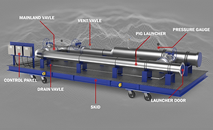
PIGGING UNIT FOR CONTAMINATION REDUCTION
Pigged pipeline technology proves advantageous for the transfer of a diverse range of products. Pigged manifolds seamlessly interconnect numerous source tanks with various destinations like filling and loading.
Addressing a significant challenge in Oil Blending Plants, pigged manifolds seamlessly interconnect numerous source tanks with various destinations like filling and loading. This innovative approach enhances efficiency and resolves complexities associated with managing multiple product transfers within the blending facility.
Pigging units serve the purpose of cleaning residual products from pipelines to prevent contamination, and they are strategically engineered to minimise the number of pipelines within a plant. The key elements of a pigging unit include the launcher, receiver, and catcher positioned at opposite ends of the pipe. A valve is incorporated to regulate the compressed air or gas utilised for propelling the pig, which travels through the pipeline to eliminate any remaining liquid. The pig can be easily inserted into or extracted from the catcher for maintenance purposes.
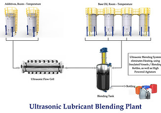
Ultrasonic Technology for Blending Plant
A groundbreaking process for blending base oil and additives utilising ultrasound technology has been established. This approach eliminates the need to heat base oils and additives, marking a notable shift from standard practices. The technology behind ultrasonic processors harnesses high-frequency sound waves to create acoustic cavitation, where small bubbles form, expand, and collapse within a liquid medium. This process effectively converts electrical energy into mechanical vibrations, known as ultrasound. This method incorporates an ultrasonic flow cell to blend the oil components effectively, yielding a uniform blend.
The ultrasonic tubular processor is designed with a 4-inch diameter and is made from stainless steel pipe. This robust design includes piezo-crystals that are fundamental to its function. The piezo-crystals create a piezo-electric effect. When powered, they collaborate with transducers to transform electrical energy into ultrasound energy.
Ultrasonic waves generate intense cavitation, which aids in the even distribution of molecules. This procedure is vital for achieving a uniform and superior blend of oils. Ultrasonic blending provides various benefits, including better energy efficiency and reduced processing times compared to standard techniques. The elimination of heating requirements simplifies the process and cuts down energy consumption, leading to a significant reduction in carbon emissions.
In larger applications, it is feasible to link several ultrasonic flow cells in a cascade arrangement. This method delivers two significant benefits: improved energy efficiency and enhanced process speed. The system not only expedites operations but also conserves resources and cuts costs, where sustainability and efficiency are crucial. This technique corresponds with the increasing need for environmentally sustainable practices in manufacturing.
Advantages of Ultrasonic Oil Blending Machinery
-
The compact design reduces the need for space.
-
Operations do not require heating.
-
Energy consumption is lower than that of conventional methods, such as heating and stirring techniques.
-
Ideal for blending in restricted spaces.
-
Ultrasonic blending is more energy-efficient for smaller batches.
-
Ultrasonic waves improve the consistency and accuracy of blends.
-
Effective distribution of additives, including nanoparticles, enhances lubrication.
-
Flexible ultrasonic systems can handle a variety of base oils and additives.
-
Environmentally sustainable production is achieved through decreased energy usage and waste reduction, significantly lowering carbon emissions.


02. VI POLYMER DISSOLVER

Viscosity Index Improver Mfg. Plant
Viscosity Index Improver Manufacturing Plant OR VI dissolver is designed to revolutionise the production process of viscosity index improvers. Built with innovation and efficiency in mind, our modular plant offers unparalleled flexibility, scalability, and performance, meeting the dynamic demands of the industry. This is used in the Engine Oil Blending Plant.
It's equipped with advanced process automation and control systems, leveraging cutting-edge technology to optimise production efficiency and product quality. From raw material handling to final product packaging, every step of the manufacturing process is meticulously monitored and controlled to ensure consistency and reliability. With a focus on sustainability, our modular plant incorporates energy-efficient technologies and waste minimisation strategies, minimising environmental impact while maximising resource utilisation. Additionally, our plant adheres to stringent quality standards and regulatory requirements, ensuring that every batch of viscosity index improver meets the highest quality specifications.
The Viscosity Index Improver Kettle is a specialised equipment used in the manufacturing process of viscosity index improvers for oil. It is designed to precisely control and optimise the viscosity index of blending oil formulations, ensuring they meet specific performance requirements.
Overall, the viscosity index improver kettle plays a critical role in the production of lubricants with optimal viscosity characteristics, contributing to the performance and longevity of machinery and equipment in various industries.
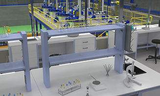
04. LABORATORY EQUIPMENT FOR TESTING LUBRICANTS
LABORATORY EQUIPMENT FOR TESTING
Laboratory testing for conducting quality assessments.
Lubricant Oil serves as the essential fluid for machinery, and analysing oil samples is crucial for evaluating the operational condition and efficiency of the equipment. Regular oil testing offers multiple advantages: it extends the lifespan of the machinery, optimises oil change schedules, and provides insights into the dynamic conditions within the equipment. This information is vital for planning maintenance activities accurately, thereby reducing the likelihood of unexpected breakdowns and minimising the risk of severe failures.
After every batch of Blended Oil, its samples are taken to the Laboratory for checking its Viscosity Index. Too high viscosity can impede flow, while excessively low viscosity may compromise parts protection.
Below is the equipment used in the Laboratory Testing:
-
VISCOSITY BATH SUITABLE TO 100 °C & 40°C
-
FLASHPOINT APPARATUS COC
-
POUR POINT 1 CHAMBER AT 51 C
-
HYDROMETER M-50 2 NOS
-
THERMOMETER-IP 51
-
TBN TITRATION APPARATUS
-
MUFFLE FURNACE
-
LAB ANALYTIC SCALE
-
LAB CHEMICALS FOR TBN
-
GLASS APPARATUS FOR LABORATORY
-
CONE PENETROMETER
-
AUTOMATIC GREASE WORKER
-
WHEEL BEARING TEST

.jpeg)
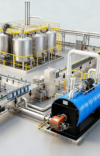
BLENDING PLANT - SECTION:
01.
BLENDING
02.
FILLING LINE
03.
UTILITY
04.
AUTOMATION
01. BLENDING SECTION


BASE OIL & RECIRCULATION PUMP
Gear pumps are essential components utilised for transferring various types of base oils from the tank farm to ABB blenders. The base oils, including SN900, SN150, SN100, and SN250, among others, are crucial raw materials for the blending process. These pumps function by utilising the meshing of gears to displace fluid, making them a prevalent choice for hydraulic fluid power applications. Gear pumps play a pivotal role in the seamless operation of projects, ensuring the efficient and precise transfer of base oils to the blending units. Their reliability, versatility, and effectiveness make them indispensable assets in the manufacturing industry, facilitating the production of high-quality lubricants for various industrial applications.
FEATURES:
1. Versatility
2. Efficient Displacement
3. Robust Construction
4. Precise Control
5. Compact Design
6. Compatibility
FINISHED PRODUCT TANK
A Finished Product Tank is an essential component in the oil manufacturing process, serving as the storage vessel for the final blended products before they are packaged and distributed. A finished product tank is a large, cylindrical container typically constructed from stainless steel or other durable materials to ensure compatibility with a wide range of formulations. These tanks are designed to hold significant volumes of finished products and are often equipped with features to maintain the quality and integrity of the stored oil.
The tank is typically located within the manufacturing facility, either adjacent to the blending area or in a dedicated storage area. It is connected to the blending equipment through piping or conveyance systems, allowing for the direct transfer of finished products from the blending vessels to the storage tank.
Finished product tanks are equipped with inlet and outlet ports that facilitate filling and dispensing. These ports may be fitted with valves or other control mechanisms to regulate the flow of oil in and out of the tank.


BASKET FILTERS
In an oil blending plant, basket filters play a crucial role in ensuring the quality and purity of the products. These filters are strategically incorporated into the processing line to remove impurities, contaminants, and solid particles from the base oils and additives before they are blended.
The basket filters typically consist of a cylindrical housing with a perforated or mesh-lined basket inside, serving as the filter element. As the base oils and additives pass through the filter housing, any particulate matter larger than the filter's mesh size is trapped inside the basket, while the clean liquid flows through. This filtration process helps to eliminate debris, dirt, and other unwanted substances that could compromise the performance and longevity of the products.
Basket filters are particularly essential in oil blending plants where precise control over the quality and composition is paramount. They ensure that the final blended formulations meet the required standards and specifications for various industrial applications. Additionally, basket filters are designed to handle the high flow rates typically encountered in the blending operations without causing significant pressure drops or disruptions to the production process. Their efficiency, reliability, and ease of maintenance make them indispensable components in the quest for producing high-quality lubricants.
LOAD CELLS
Load cells serve as critical components for precisely measuring the weight of ingredients during the blending process. These specialised sensors are integrated into the blending equipment to ensure accurate and consistent formulation of products. Load cells are typically installed beneath the blending vessels or tanks where the base oils, additives, and other ingredients are mixed. As the ingredients are dispensed into the blending vessel, the load cells detect and measure the weight of each component in real-time.
This information is then relayed to the control system of the blending plant, allowing operators to monitor and adjust the ingredient ratios as necessary to achieve the desired lubricant formulations. Load cells are calibrated to withstand the harsh operating conditions within the blending plant, including variations in temperature, pressure, and vibration. They provide precise measurements with high levels of accuracy, ensuring that the final products meet the required specifications and quality standards. Additionally, load cells offer advantages such as rapid response times, minimal maintenance requirements, and compatibility with various blending processes. Overall, load cells play a crucial role in optimising the efficiency, consistency, and quality of blending plants by enabling precise control over ingredient dosing and formulation.
Load cells offer several advantages:
1. Built-in Safety: They provide inherent safety measures against vessel tilting and build forces, ensuring stability during operations.
2. Thermal Flexibility: Load cells accommodate vessels' expansion and contraction caused by thermal effects, maintaining accurate measurements despite temperature fluctuations.
3. Copper Earthing Strip: Equipped with a flexible copper earthing strip, load cells are safeguarded against lightning strikes or welding currents, enhancing their durability and reliability.
4. Cable Protection: They feature built-in load cell cable protection plates and overload protection plates, along with heat insulation pads, to shield against external damage and ensure uninterrupted performance.


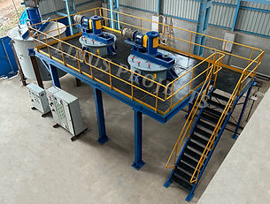
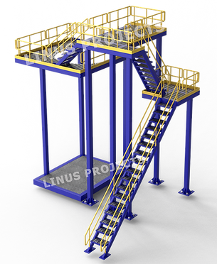
PLATFORM / STRUCTURE
The platform or structure of an oil blending plant is meticulously engineered to provide a robust foundation and support system for intricate blending operations. Constructed from durable materials such as steel or concrete, it is designed to withstand the rigours of industrial environments and ensure the safety and stability of the entire facility. The platform's layout is carefully planned to optimise workflow and accommodate various components and equipment essential for the blending process.
At its core, the platform serves as a sturdy base for housing blending vessels, which are the heart of the operation. These vessels are securely positioned on the platform, allowing for efficient mixing of base oils, additives. Additionally, the platform supports the installation of mixing equipment, such as agitators or stirrers, which are instrumental in achieving uniform blending and consistency in the final product.
In addition to the blending vessels and mixing equipment, the platform accommodates piping systems that transport raw materials and finished products throughout the facility. This includes pipelines for delivering base oils and additives to the blending vessels, as well as conduits for transferring blended oil to storage tanks or packaging lines. Moreover, the platform may incorporate elevated platforms or walkways, providing convenient access to equipment for maintenance, inspection, and monitoring purposes. These elevated structures enhance operational efficiency and ensure the safety of personnel working within the facility.
Importantly, the platform is engineered to mitigate the effects of heavy machinery and equipment vibrations, as well as dynamic loads associated with blending operations. This ensures the structural integrity of the facility and minimises the risk of equipment damage or malfunction. Overall, the platform serves as a critical infrastructure element in the blending plant, facilitating efficient, safe, and reliable production processes. Its robust construction, strategic layout, and adherence to safety standards contribute to the smooth operation and longevity of the blending facility.
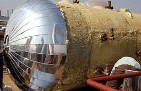
INSULATION FOR BLENDING TANKS
Insulation of blenders helps in maintaining optimal operating conditions and enhances efficiency in the blending process. Here's a description of the insulation typically used for blenders:
Blender insulation is designed to minimise heat loss and maintain consistent temperatures within the blending vessel during the mixing process. This insulation is applied to the exterior surface of the blender's main body and jacket, providing a thermal barrier that prevents heat from escaping or entering the vessel.
The insulation material is often composed of high-quality materials such as rock wool, fibreglass, or mineral wool, known for their excellent thermal insulating properties. These materials are chosen for their ability to withstand high temperatures and resist degradation over time, ensuring long-lasting performance in demanding industrial environments.
The insulation is carefully applied to the blender's exterior using a combination of techniques such as wrapping, spraying, or cladding, depending on the specific design and requirements of the blender. It is custom-fitted to the shape and size of the blender, ensuring complete coverage and effective thermal protection.
Overall, insulation for blenders plays a crucial role in optimising energy efficiency, reducing heat loss, and maintaining precise temperature control during blending operations.
02. FILLING PACKAGING SECTION


LUBRICANT FILLING MACHINE
Filling machines play an essential role in the packaging process, ensuring efficient and accurate filling of oil products into containers of various sizes. These machines are designed to handle the specific requirements of oil blending operations and are tailored to meet the demands of high-volume production.
The filling machine of Linus Projects used in blending plants is a precision-engineered piece of equipment designed to fill containers with oil products with precision and consistency. It typically consists of a conveyor system that transports empty containers to the filling station, where they are filled with the desired amount of oil.
The filling machine is equipped with multiple filling heads to increase throughput and efficiency, allowing for the simultaneous filling of various containers. These filling heads are designed to accommodate different container sizes and shapes, ensuring versatility and flexibility in production. Depending on the specific requirements of the blending plant, the filling machine may operate in either automatic or semi-automatic mode.
In automatic mode, the filling process is fully automated, with containers being filled, capped, and labelled without the need for manual intervention.
In semi-automatic mode, operators oversee the filling process and manually control certain aspects of the operation.
Filling Range : 500 ml to 5 litres
Number of Filling Heads : 2 to 14 Heads
Filling Mode : Automatic / Semi Automatic
Application : Lubricant Oil, Engine Oil
FEATURES:
1. High-Speed Operation
2. Versatility
3. Precision Filling
4. Automated Operation
5. Programmable Controls
6. Safety Features
7. Easy Maintenance
8. Robust Construction
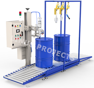
DRUM FILLING MACHINE
The Barrel Filling machine is a critical piece of equipment designed to efficiently and accurately fill barrels with oil. This machine plays a vital role in the packaging process, ensuring that each barrel is filled to the correct level with the precise amount of oil required. It operates seamlessly within the production line, contributing to the overall efficiency and effectiveness of the plant's operations.
Utilising advanced technology and precise mechanisms, the barrel filling machine precisely dispenses oil into each barrel, minimising wastage and ensuring consistent product quality. Its automated operation streamlines the filling process, allowing for high throughput and minimising downtime.
Equipped with intuitive controls and monitoring systems, the barrel filling machine offers operators the ability to adjust filling parameters and monitor production in real-time. This ensures accurate filling levels and enables quick adjustments to accommodate different barrel sizes or product specifications.
Additionally, the barrel filling machine is designed with safety features to prevent spills, leaks, and other potential hazards during the filling process. Robust construction and durable materials ensure reliability and longevity, even under heavy-duty usage in industrial settings.
Our drum-filling machine is suitable for filling 25 litres, and it is fully adjustable.


LUBRICANT BOTTLE CAPPING MACHINE
The capping machine stands as a pivotal element, serving as the linchpin of the packaging process. Its primary function revolves around the secure sealing of containers that are filled with oil. As the final step before distribution, the capping machine ensures that each can is appropriately sealed, safeguarding the integrity of the product within.
Our capping machine comprises a Cap Vibrator for cap orientation & a capping unit. The caps fed into the vibratory hopper are properly oriented here. The properly oriented caps are brought out through the chute and supported at the end by spring-loaded fingers. The containers, as they come out of the filling station, move to the capping unit, where they pick up the cap and go towards the capping head. The caps are subsequently tightened through a magnetic clutch system. The capped bottles finally emerge from the machine through a discharge conveyor.
With meticulous precision, the capping machine applies caps onto the filled cans, guaranteeing a snug fit that prevents any leakage or spillage during handling and transportation. This process is executed with utmost accuracy, ensuring that each cap is affixed uniformly and securely onto every can. The capping machine is designed to accommodate various types and sizes of caps commonly utilised within the industry. Whether it's screw caps, snap caps, or press-on caps, the capping machine seamlessly adapts to the specific requirements of the packaging, ensuring compatibility with diverse packaging needs.
FEATURES:
1. Versatility
2. High-Speed Operation
3. Precision Capping
4. Adjustable Torque
5. Automated Operation
6. Integrated Controls
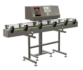
INDUCTION SEALING MACHINE
The induction sealing machine is an essential component of the packaging process, responsible for securely sealing containers filled with oil.
The induction sealing machine serves as a critical safeguard in the final stages of packaging, ensuring that each container is hermetically sealed to preserve the integrity of the blended oil products within. Its operation seamlessly integrates into the packaging line, providing a reliable and efficient means of applying tamper-evident seals to containers.
Utilising advanced induction heating technology, the sealing machine creates a strong and airtight seal between the container and its closure, effectively preventing tampering, leakage, and contamination. As containers pass through the machine, an electromagnetic field is generated, causing the foil liner on the closure to heat and bond with the container's rim, forming a secure seal.
The induction sealing machine operates with precision and speed, keeping pace with the high-volume production rates within the oil blending plant. Its efficient performance ensures seamless integration into the packaging line, contributing to overall productivity and throughput.
Equipped with intuitive controls and user-friendly interfaces, the sealing machine offers ease of operation, allowing operators to adjust sealing parameters and monitor the process with accuracy. This ensures consistent and reliable sealing performance, meeting stringent quality standards and regulatory requirements.

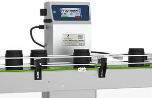

INK JET / LASER PRINTER
Automatic solution for printing batch identification codes, MRP, best before and packaged dates, plus QR codes onto almost any material, including specialist applications such as food and metals. CIJ coding & marking machines offer high-speed, reliable batch, lot, MRP & date coding for product identification and traceability. Our continuous ink jet batch printing machines can code onto a wide range of materials, even in dusty, hot, and wet environments.
The inkjet printer is responsible for imprinting essential information such as batch numbers, expiration dates, and product codes onto the containers filled with blended oil products.
The inkjet printer stands as a key player in the final stages of production, ensuring that each container leaving the facility is appropriately labelled with critical information. As the containers move along the packaging line, the inkjet printer seamlessly integrates into the process, providing a swift and efficient means of marking essential details onto the packaging.
Utilising advanced inkjet printing technology, the printer precisely deposits ink onto the surface of the containers, creating clear and legible markings that withstand handling and storage. This method offers unparalleled versatility, allowing for the customisation of text, symbols, and graphics to meet specific labelling requirements.
BOTTLE LABELLING MACHINE
The labelling machine in an oil blending plant is a crucial component of the packaging process, responsible for applying informative and branding labels onto containers filled with blended oil products.
Situated within the bustling confines of the oil blending plant, the labelling machine stands as a pivotal player in the final stages of production, ensuring that each container leaving the facility is accurately and attractively labelled. As containers journey along the packaging line, the labelling machine seamlessly integrates into the process, providing a swift and efficient means of applying labels onto the packaging.
Employing advanced labelling technology, the machine precisely affixes labels onto containers with precision and accuracy, creating a professional and polished appearance. This method offers versatility, allowing for the application of various types of labels, including product information, branding, barcodes, and regulatory compliance labels.
Furthermore, the labelling machine is designed for reliability and durability, capable of withstanding the demanding conditions of industrial environments. Its robust construction and advanced technology ensure consistent performance, minimising downtime and maximising uptime to meet production deadlines effectively.


CARTON TAPING MACHINE
The Carton taping machine stands as an indispensable workhorse in the final stages of the packaging process. Tasked with the critical responsibility of securely sealing cartons filled with products, this machine executes its duty with precision and reliability.
As each carton makes its way through the production line, the carton taping machine springs into action, seamlessly and efficiently sealing the cartons to safeguard the integrity of the contents within. With deft precision, it applies adhesive tape along the seams of the cartons, ensuring a firm and durable seal that withstands the rigours of storage and transportation.
By adeptly sealing the cartons, the machine plays a vital role in preserving the quality and integrity of the blended oil products housed within. It shields them from potential damage, contamination, or tampering, ensuring that they reach their destination in pristine condition, ready to fulfil their intended purpose.
In essence, the carton taping machine serves as a silent guardian of product quality and customer satisfaction within the oil blending plant. Its steadfast operation and unwavering reliability underscore its indispensable role in the packaging process, making it an essential asset in the plant's arsenal of equipment.
Carton size in mm (L x W x H): 150 X 150 X 100 (Min) X 450 X 500 (Max)
Carton Weight : maximum 25 Kgs.
Speed - No. Of cartons / hr : 200 - 800
Machine bed height : 600 – 800 mm
Tape width : 48 mm. (2")
Tape overlaps : 50 mm.
Tape Core diameter :75 mm.
03. UTILITY

THERMIC FLUID HEATER
Linus Projects specialises in providing top-quality, fuel-efficient burners paired with boilers, catering to both steam and thermic fluid applications. The core heating unit comprises a robust double-jacketed external shell crafted from sturdy M.S. Sheets. It incorporates an aluminium reflector, serving to preheat the combustion air while also offering efficient heat insulation.
The heart of the system features specially engineered multi-start, concentric helical coil assemblies constructed from B.S. 3059, Part I, 9 Gauge, Boiler Tubes. This design ensures prolonged operational life and exceptional performance, even in high-temperature environments.
For combustion, the setup integrates a pressure jet burner assembly from RIELLO ITALY, renowned for its reliability and efficiency. This burner assembly includes an integral oil pump and combustion blower assembly driven by a motor, facilitating seamless on/off control for optimal operational efficiency.
The Thermic boiler, also known as a thermal fluid heater or thermal oil heater, is a specialised type of industrial boiler designed to generate heat by heating a thermal fluid, typically a heat transfer oil. This fluid circulates through the boiler system, transferring heat to various components of the oil blending process, such as heating tanks, blending vessels, and reactors.
Constructed from high-quality materials such as stainless steel or carbon steel, the thermic boiler features a robust outer shell designed to withstand high temperatures and pressure. Inside the boiler, a series of heating coils or tubes is immersed in the thermal fluid, facilitating the transfer of heat from the combustion chamber to the fluid.
The boiler system is equipped with a burner unit responsible for combusting fuel, such as natural gas, diesel, or heavy oil, to generate heat. The combustion process heats the thermal fluid circulating within the boiler, raising its temperature to the desired level for the blending process.
FEATURES:
1. High Thermal Efficiency
2. Wide Temperature Range
3. Versatility
4. Compact Design
5. Advanced Control Systems
6. Environmental Considerations
03. ADDITIVE DRUM DECANTING UNITS
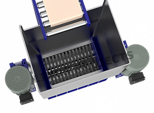
DRUM DECANTING UNIT (DDU)
Drum Decanting Unit (DDU) represents a mechanised and automated solution for introducing small-volume additives into blends. These units come equipped with conveyor belts, load cells, control systems, rinse tanks, and swivel lances. Drum Decanting Units contribute to heightened efficiency and safety. The DDU is meticulously engineered for pumping and precisely dosing highly viscous liquids from drums, seamlessly integrating them into formulation processes. This technology is particularly recommended for scenarios demanding the utmost accuracy in dosing and repeatability.
The Drum Decanting Unit can be used to empty a defined value of additives without cross-contamination into the oil production process. The product has various operational features, including decanting, rinsing, drum tilting, and heating. The high-performance DDU integrates the expensive additive into the production process without causing product loss, waste oil onset, or high-precision dosing errors through weighing technology. The unit is easy to handle, satisfies the highest safety standards, and runs in clean and completely closed conditions.
LINUS PROJECTS(INDIA) Drum Decanting Unit can be used for emptying a defined value of additives without any cross-contamination into the production process.
The product has various operational features, including decanting, rinsing, drum tilting, and heating.
The high-performance DDU integrates the expensive additive into the production process without causing product loss, waste oil onset, or high-precision dosing errors through weighing technology. The unit is easy to handle, satisfies the highest safety standards, and runs in clean and completely closed conditions.
Operation of DDU:
A typical DDU uses roller conveyors to feed and discharge the drums or totes - one at a time - onto the drum-weighing platform.
-
The proper drum is selected and fed into the platform in sequence by the operator.
-
The platform is mounted on compression load cells that weigh the amount of each material, and a tilting device is included to ensure maximum product recovery and removal.
-
Additionally, a suction telescopic nozzle, equipped with a flexible hose, is inserted into the drum to withdraw the liquid.
-
A screw Pump is provided to suck the oil and transfer it to the dosing or blending system.
-
The operator initiates production using the supervisory Control System, which pulls and verifies the component recipe and line-up.
-
When the set amount of material has been withdrawn from each drum, the lance is removed, cleaned in a rinsing tube and restored for the next drum in sequence.
-
A rinse tank equipped with a heating system is included.
-
The system flushes the nozzle and drum to remove any remaining material, ensuring maximum product recovery and minimising waste or cross-contamination.
-
Additionally, each empty drum is rinsed with a low viscosity component to minimise any residual material in the drum or tote.
-
A separate hose with a quick-release coupling is provided to add the finishing oil from any system at a particular time.
Advantages of our Drum Decanting Unit:
-
Exact, reliable, and reproducible dosing of additives in the production process
-
Saving additives by emptying the drums.
-
No waste oil in the production process
-
No cross-contamination by cleaning the drum with hot rinse oil.
FEATURES AND BENEFITS OF OUR DDU
-
Eliminate manual dosing, cleaning, and overtreating for safer, efficient operations with the fully automated system, including Clean-In-Place technologies
-
Maximise product recovery and removal with tilting devices to empty drums.
-
Increase flexibility by accommodating additives with a wide viscosity range or by manually adding components as required by the recipe.
-
Avoid over-treating through accurate dosing
-
measures set to the computation of the decanting operation.
-
Directly blend components packaged in drums or totes.
-
Reduce footprint with a newly enhanced, more compact unit.
-
Increase operational efficiency by selecting up to 9 different control phases based on recipe requirements
-
No contamination of the rinse tank by lance cleaning.


IBC DECANTING UNIT (IBC)
Intermediate Bulk Container Tank Decanting Machine is a specialized piece of equipment engineered to efficiently and safely transfer liquids from IBC tanks. Designed to meet the rigorous demands of various industries, this decanting machine is indispensable in sectors such as lubricants, grease, chemical manufacturing, food and beverage processing, pharmaceuticals, and any application where bulk liquid handling is necessary.
IBC decanting machine offers both pneumatic and hydraulic options, providing flexibility and reliability in its operation. At the heart of the system is a vertically mounted screw pump, capable of transferring liquids at a rate of up to 2000 liters per hour (LPH). This robust pump system is available with power capacities ranging from 1HP to 5HP, ensuring it can handle a wide range of liquid viscosities and transfer needs. Equipped with advanced Programmable Logic Controllers (PLC) and Human Machine Interface (HMI) options, allowing for enhanced control, automation, and ease of use based on specific requirements.
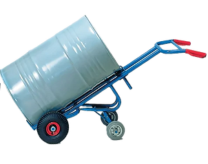
DRUM TROLLEY
Drum Trolley is a specialized handling equipment designed to transport and maneuver drums safely and efficiently within industrial environments.
Drum holder: by means of fabricated belt & pipe with positive gripping.
Structure: simplex single mast structure made from heavy-duty ‘c’ channel section. It would be supported by heavy-duty deep grooved guide rollers. Forks lifting would be by means of 2nos. Duplex chain & design pulley.
Handle: designed for best maneuverability & made of M. S. Pipe.
Wheel: 8” x 2” nylon swivel castor wheel with 6204zz double ball bearing
Paint: auto-finish paint.

DRUM LIFTER & TILTER
Drum lifters and tilters play a vital role in the industrial sector, particularly in loading, unloading, and emptying drums used in various applications such as engineering and oil blending plant. These essential pieces of equipment are indispensable for efficiently handling drums, ensuring precise measurement and controlled pouring of contents into blenders or other processing equipment.
At the heart of a drum lifter and tilter is its robust construction, comprising a carriage assembly, hydraulic system, and hydraulic cylinder. The carriage assembly provides a stable platform for securely gripping and lifting drums, while the hydraulic system facilitates smooth and controlled lifting and tilting operations. The hydraulic cylinder is the powerhouse of the equipment, responsible for exerting the necessary force to lift and tilt heavy drums with ease.
Whether it's transferring base oil for blending or handling other industrial materials, drum lifters and tilters are indispensable tools for maintaining operational efficiency and productivity. Their reliable performance, ergonomic design, and safety features make them essential equipment for any facility where drums are a common sight. With their ability to handle heavy loads with ease and precision, drum lifters and tilters are indispensable assets in modern industrial operations.
DRUM HEATING OVEN FOR ADDITIVES
The Drum Heating Oven is engineered to enhance the efficiency and ease of your industrial operations by offering a straightforward and dependable solution for heating and regulating the temperature of materials contained in drums or barrels. Whether dealing with oils, chemicals, resins, or other substances requiring accurate temperature management, this oven guarantees uniform and consistent heating, thereby alleviating the challenges associated with manual heating techniques or variable outcomes.
Drum heating ovens are constructed from robust materials designed to endure the demands of industrial applications. They also offer energy efficiency, allowing for a reduction in energy usage while ensuring peak performance. Additionally, equipped with safety features such as insulated doors and thermal shut-offs, these ovens provide a reliable and secure operational environment.
In short, a drum heating oven not only enhances time management but also guarantees that your materials are prepared for use precisely when required, thereby streamlining and optimizing your production process.
Manufacturing Many Types of Drum Heating Ovens.
-
Electric Cabinet Ovens for Drum & Barrel Heating Ovens.
-
Steam Drum Heating Oven.
-
Drum Spinning Heating Oven.
-
Temperature Control & Flameproof Sensors Drums Heating Oven.
-
Thermic Fluid Drum Heating Oven.


PALLET TRUCK
Manual Pallet Trucks Which Are Supplied In Rounds, Flats N Plates Sections. Hand Pallet Trucks Manual & Hydraulic Are Used to By Major Industrial Units Hand. Pallet Trucks Manual & Electric Is Being Supplied to The Consumers.
A pallet truck, also known as a pallet jack or pump truck, is a manual or electrically powered device used for lifting and moving palletized loads within warehouses, distribution centers, and other industrial settings
- Forks and Load Capacity
- Pump Handle
- Load Rollers and Wheels
- Lowering Lever
- Compact Design
- Versatile Applications
AIR COMPRESSOR
An air compressor serves as the backbone of operations within a oil plant, offering essential compressed air to power an array of pneumatic tools, machinery, and vital processes throughout the facility. Its role is indispensable, supporting the seamless functioning of various operations within the plant.
At the core of its functionality, the air compressor acts as the primary source for generating compressed air, a vital utility used extensively within the plant premises. This compressed air serves as the driving force behind pneumatic tools, facilitating tasks ranging from equipment maintenance to assembly line operations with precision and efficiency.
Installed strategically within the plant, the air compressor operates tirelessly, ensuring a steady and reliable supply of compressed air to meet the diverse demands of pneumatic equipment and processes. Whether it's powering pneumatic drills, wrenches, or other tools used for maintenance activities, or providing the necessary force for pneumatic actuators in machinery and conveyors, the air compressor plays a critical role in keeping operations running smoothly.

04. AUTOMATION
SCADA PLC & MCC ELECTRICAL PANEL
The electrical panel is designed to operate all electrical motors efficiently and safely. Enclosed within a sturdy sheet steel powder-coated enclosure, it comes pre-wired for convenience. Equipped with a Motor Control Centre (MCC) panel, it features a remote push button station for motor control. In case of any anomalies with the motors, the panel automatically trips to prevent damage, ensuring their safety. Premium quality switches from reputable brands such as L&T are incorporated for reliable operation. Additionally, the panel includes R-Y-B lamps, as well as digital ammeters and voltmeters for accurate monitoring of electrical parameters. Overall, this electrical control panel offers a comprehensive solution for managing motor operations in industrial settings.
The PLC (Programmable Logic Controller) & MCC (Motor Control Centre) electrical panel is a comprehensive control system utilised in industrial settings to manage and regulate electrical equipment and machinery. It integrates sophisticated technology to streamline operations, enhance safety, and optimise efficiency within industrial facilities.
At the heart of the system lies the Programmable Logic Controller (PLC), a robust computing device tailored for industrial automation. The PLC serves as the central processing unit, executing pre-programmed instructions to control a wide array of electrical components seamlessly. With its programmable nature, the PLC allows for customisation of logic and sequencing, enabling precise and reliable automation of complex processes.
The Motor Control Centre (MCC) component of the panel acts as a centralised hub for motor management. It houses motor starters, contactors, relays, and other essential devices, facilitating the control and operation of electric motors throughout the facility. The MCC ensures efficient motor performance while providing overload protection, short-circuit protection, and fault detection capabilities to safeguard equipment and personnel.
OPERATION SEQUENCE & LOGIC Selection & Settings:
-
Selection of the Storage tank & Blender for transfer is done through HMI and PLC.
-
The setting of parameters, like the weight of each ingredient, is handled by the recipe management system.
-
The setting of other parameters, such as time specifications. Etc.
The Operation Starts from the HMI:
-
Start the operation by selecting the above parameters.
-
Respective valves & pumps will be operated in that sequence after fulfilment of the required interlocks.
-
Operation sequencing will be done as per the valve status.
-
Valve, Motor and Pump status will be displayed on the HMI with colour animation
-
The current value of weight will be displayed continuously.
-
Faults & alarms will be displayed upon arrival, including date & time stamping. Also, it will be stored.
-
Data will be logged in the HMI (Which can be used for future analysis)
-
Manual ON/OFF is also possible through HMI (Individual opening/closing of the valves)


.jpeg)

WEST AFRICA - Nigeria - LUBE OIL BUSINESS GROWTH & AUTOMATION TECHNOLOGY
Nigeria is a major exporter of crude oil and petroleum products to various countries. We will delve into the country's rich oil reserves, its production capabilities, and discuss the challenges and opportunities that Nigeria faces. Nigeria's efforts to expand its industrial sector and improve its infrastructure have led to a significant increase in the demand for Blending Oil.
-
Exploring the Impact of Nigeria's Industrial Growth on the Demand for Blending Oil.
-
The Role of Engine Oil in Enhancing Efficiency in Nigeria's Automotive Industry, Manufacturing and Construction Sectors.
-
How Nigeria's Infrastructure Development is Driving the Market for Blending Oil.