

LUBRICANT BLENDER
Linus Projects supply high quality Lubricant blending plant and machinery.

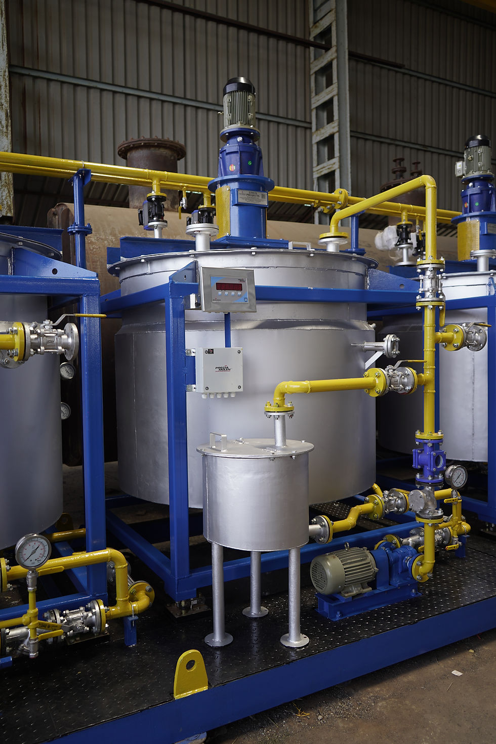
Lubricant Oil Blender

Linus Projects supply high quality Viscosity index manufacturing of VI kettle. Our products are very much competitive in pricing.
Linus Projects supply high quality Lubricant blending plant and machinery.

Agitator arrangement of Lubricant blender.
Agitator arrangement of Lubricant blender.
LUBE OIL BLENDER
Linus Projects takes pride in manufacturing high-quality and meticulously designed lubricant blenders, tailored for blending viscous liquids, base oils with additives, engine oils, gear oils, and industrial oils. Our lubricant blenders, integral to Lube Oil Blending Plants, are crafted with precision to uphold reliability, consistency, and top-notch quality in every blending operation. With a commitment to delivering premium service and top-quality blenders globally, we empower our customers to fulfill their promises to their clients.
Our lubricant blenders feature a vertical mixing vessel constructed from Mild Steel IS 2062 material. The open-top design with a partial dished bottom ensures efficient blending. The blender is equipped with a hinged top lid, providing easy access to the main vessel. A ball valve for discharge, along with a sample valve, enhances operational convenience. An MS Jacket surrounds the main blender, complete with inlet, outlet, drain, and vent fittings, allowing precise temperature control. The blender is strategically mounted on load cells for automation and PLC operation, ensuring accurate blending processes. Temp probes with necessary fittings further contribute to operational efficiency.
The drive system is a robust assembly featuring an electric motor coupled to a heavy-duty gearbox through couplings. The gearbox's output shaft connects to a stool housing with bearings, oil seals, and gland packings, ensuring smooth and reliable operation. This entire drive assembly is securely mounted on a sturdy frame structure, providing stability and longevity. The top cover, of the flat hinged type, is bolted to the main shell, facilitating easy access for charging base oils, recirculation, and solids loading through a manhole cover.
A shell jacket is integrated into the design to maintain an efficient cooling system during the blending process. The kettle is engineered to withstand temperatures up to 200˚C, providing versatility for various blending applications. Furthermore, the kettle is insulated with rock wool and clad with GI sheets for enhanced thermal efficiency.
LUBE BLENDER
At Linus Projects, we are at the forefront of delivering precision and excellence in the field of lubricant manufacturing. Our Lube Oil Blender stands as a testament to our commitment to top-tier quality and innovative design. Meticulously crafted for blending high-quality viscous liquids, base oils with additives, engine oils, gear oils, and industrial oils, our blender is an indispensable asset within Lube Oil Blending Plants.
FEATURES:
-
The Lube Oil Blender is constructed with precision using Mild Steel material, ensuring durability and longevity. The vertical shape mixing vessel with an open top and partial dished bottom facilitates efficient blending.
-
Crafted to meet diverse blending requirements, our blender comes in various capacities fabricated from Mild Steel material.The open-top design and partial dished bottom provide versatility in accommodating different volumes and types of lubricant formulations.
-
An MS Jacket surrounds the main blender, equipped with inlet, outlet, drain, and vent fittings. This advanced jacketing system allows precise temperature control, a crucial aspect in achieving optimal blending conditions.
-
To enhance operational efficiency, the blender is mounted on load cells for automation and PLC operation.
-
The drive system comprises an electric motor coupled to a heavy-duty gearbox through couplings.
-
The blender is designed to withstand temperatures of up to 200˚C, making it suitable for a wide range of lubricant blending applications


MOTOR GEARBOX
Eco-Friendly Design
Lube Oil Blender lies a sophisticated and reliable Motor Gearbox integration, seamlessly marrying power with precision. Engineered for efficiency and durability, this vital component plays a pivotal role in driving the blending process within Lube Oil Blending Plants. As a cornerstone of our commitment to excellence, the Motor Gearbox integration ensures optimal performance and consistency in every blend.
FEATURES:
-
Robust Motor Integration
-
Heavy-Duty Gearbox
-
Couplings for Seamless Connection
-
Output Shaft to Stool Housing
-
Sturdy Frame Structure
-
Precise Blending Control
-
Automation Compatibility
-
Reduced Downtime
AEROFOIL BLADE DESIGN
The Aerofoil Blade Design takes center stage in the agitator system of Lube Oil Blender. Inspired by the efficiency of wind turbine technology, this blade design redefines the dynamics of blending viscous liquids, base oils with additives, and industrial oils. Merging precision aerodynamics with industrial functionality, the Aerofoil Blade Design optimizes the blending process, ensuring consistency, reliability, and elevated performance within Lube Oil Blending Plants.
FEATURES:
-
The Aerofoil Blade Design draws inspiration from aerospace engineering, embodying a level of precision and efficiency previously unseen in industrial blending.
-
Crafted with a focus on fluid dynamics, the Aerofoil blades introduce a streamlined form that facilitates seamless fluid movement within the blending vessel.
-
Aerofoil blades incorporate variable pitch technology, allowing dynamic adjustments to blade angles based on the viscosity of the materials being blended.
-
Constructed from high-strength materials, the Aerofoil blades provide structural robustness, capable of withstanding the demands of industrial blending.
-
Meticulously designed to minimize shear stress on blended materials, the Aerofoil blades preserve the integrity of sensitive additives.
-
The blender is designed to withstand temperatures of up to 200˚C, making it suitable for a wide range of lubricant blending applications


ELECTRIC HEATER
Eco-Friendly Design
One crucial component contributing to the precision of their Lube Oil Blender is the strategic integration of electric heaters. This write-up delves into the significance of electric heaters within Linus Projects' Lube Oil Blender, highlighting their role in maintaining optimal temperatures for blending viscous liquids, base oils with additives, and industrial oils.
FEATURES:
-
Temperature Homogeneity
-
Rapid Heating Response
-
Adaptive Heating for Varying Viscosities
-
Energy Efficiency
-
Controlled and Consistent Processes
-
Efficient Resource Utilization